 Prev
Next
 Site Map
 Home
Home
| . | . | . | . | David McCracken |
Thera Institute Software Engineerupdated:2018.10.13 |
Thera Institute is a non-profit energy research and education company. Most of its research involves chemistry and biology but it had a new initiative to investigate industrial use of diffuse sunlight. The Earth receives far more energy from the sun in the form of diffuse than direct sunlight but we have no means of concentrating it for controlled distribution. If this could be done economically it could potentially transform every exposed surface into an industrial energy source.
Inventors and scientists routinely claim to have discovered how to concentrate diffuse light but none of the claims stand up under scrutiny. Some physicists argue that it is theoretically impossible. Thera scientists agreed that the publicized solutions were scientifically unsound but did not entirely agree with the physicists either. One of the main arguments draws a thermodynamic distinction between diffuse and collimated (direct) light. This is obviously wrong. A fundamental premise of thermodynamics is that path is irrelevant.
Thera scientists partially agreed with another objection, which is that quantum information is lost when portions of a wave traverse different paths. The increased entropy of the wave cannot be reversed without adding energy. However, they disagreed on two points, one theoretical and the other practical. The theoretical disagreement is motivated by the fact that a lens can focus off-axis (non-paraxial) beams. Incident diffuse light from a single source can be considered an infinite number of beams at different angles. Since each of these can be individually focused, some or all original information must still exist. This is similar to the concept of spread-spectrum communication, which, despite its random appearance, conveys the same amount of information in a given bandwidth as dedicated channels.
The practical issue is that the quantum information argument, even if correct, would only preclude focusing, which is not a requirement for solar energy collection. In fact, it would be better to only concentrate the light, that is to redirect it all to a single point but not in phase. The positive superposition of truly focused waves would create a hot spot that could easily damage a concentrator.
Thera scientists envisioned a diffuse solar collector comprising a laminated stack of thin clear plastic sheets, each embossed with millions of tiny lens elements. Incident sunlight would be collimated by refraction in the top layer and turned sideways and concentrated by reflection in subsequent layers, eventually exiting through a single optical port. Existing optics design programs could help with some of this but none of them do anything with diffuse light and the only known reference to this is in the standard physics discussion of infinitely thin spherical lenses. Thera scientists wanted me to develop a program that would enable them to investigate designs limited only by fundamental physics rather than the rules of thumb that inform most optics design programs.
I designed the program, dubbed Optopus, as two independent subsystems, a math engine and a GUI. The GUI has some typical convenience items, such as directly invoking various functions, but it is otherwise highly interactive. For example, ray tracing results are displayed in real time as the user slides a control to change the shape of a lens face. The GUI calls on the math engine to analyze a lens being displayed. Some of the math functions calculate extra information beyond their main purpose for the benefit of the GUI, but the additional work is minimal. Having the same function serve both the GUI and non- GUI operations reduces code redundancy while improving testability. Unit testing is easier with a generic interface than with one dedicated to the requirements of the GUI while the interactive use of the functions provides a user-based sanity check that would be difficult to codify.
Thera scientists wanted the program to run under Windows but didn’t care how it was developed and had no use at all for modern bells and whistles. I chose Win32 API because it starts and runs fast and rarely encounters the kinds of version problems that can afflict managed code.
Other than the requirement to trace diffuse light, which is not conceptually difficult, I initially assumed that the math engine would be generally similar to commercial and open source programs. However, reviewing these programs, I found that most were directed toward ray tracing through multiple elements and provided little opportunity to explore a single lens in great detail. Some even handled only spherical lenses. The ones that did handle aspheres seemed mathematically primitive, either approximating lens curves by enumerating many points or using Taylor series. None seemed to have deterministic curve functions derived from fundamental principles.
In software development, non-deterministic solutions are initially easy but become overgrown and difficult to comprehend over time. The effort to develop deterministic alternatives at the beginning ultimately saves time and may enable new capabilities otherwise unattainable. For examples, see my IDT touch pointer displacement acceleration or my algorithm transformation for Abbott. This is even truer for math than it is for programming. Only symbolic deterministic equations can serve as building blocks for more complex problems. Non-deterministic solutions are dead ends theoretically. They also present a practical problem, in having no real answer. The answer depends on system resolution and how long we are willing to wait. It is difficult to convey such an answer, for example, to a fabricator.
Thera scientists agreed with my concerns about standard lens math, which seems to be based more on rules of thumb than a strong theoretical foundation, and added that we couldn’t trust these rules to optimally support the new kinds of optical interactions that we were anticipating. However, they didn’t have any specific suggestions and left it up to me to try to develop a better math foundation.
I decided that we needed an incontrovertible core capability to serve as the method of last resort and to stimulate theoretical math analysis. I chose to base this on Snell’s law of refraction because that can be applied at any point with minimal context. Snell’s law tells how a light ray will bend at the interface between two mediums, for example from air into transparent plastic. Incident and refracted ray angles are relative to normal, which is a right angle to the lens face. In ray tracing, the lens face angle will be known but its normal is imaginary and just adds useless complexity to expressions so I mathematically proved a modified version of the law based on the face angle instead of its normal. Although the law is applied at one point, it involves angles, which don’t exist without context beyond the point. The incident angle is given and we are computing the refracted, leaving only the face angle to be determined. If the face were defined by a function, its slope (i.e. angle) could be computed. But the purpose here is to discover the ideal face without any preconceived notion of its shape. I solved this conundrum by using my face refraction law in a process of stepping from the apex of the lens, where the face slope is 0 by definition, to the lens right edge. At each point, the slope is the left derivative relative to the previous point. The overall face curve is not necessarily defined by a differentiable function.
It is not an oversight that the core process doesn’t specify what constitutes an “ideal” face. That is to be determined, in much the same way that the standard library quick sort doesn’t know what it is sorting and relies on a given comparison function to determine the relative order of any two elements.
I first applied this universal core to finding the ideal shape for a single-face lens of a given focal length (for a paraxial beam). At each step across the face, the drop from the apex is non-deterministically found by searching for the point where applying the face refraction formula produces a ray that intersects the lens axis at the desired focal length. This could serve as a method of last resort, computing an enumerated curve, but the resulting curves clearly were continuous and differentiable. Regardless of specific focal length, the ideal lens face was always less strongly curved near the edges than a circle. Therefore, the function could not be cyclical (e.g. circle, spiral, cycloid). Comparing it to asymptotic functions (e.g. parabola, logarithmic, exponential) the ideal was clearly more strongly curved near the edges. Only an ellipse affords sufficient curve control to fit within these bounds. Further, it was evident that the lens axis is always the major axis of the ellipse; that the focal point is the ellipse’s trailing (in the light path) focus; and that the eccentricity of the ellipse is equal to the ratio of indices of refraction. I was not expecting such a simple relationship and could find no references to it in optics literature. Even without proof it would serve the practical purpose of describing a required shape by function rather than by enumeration or infinite series. Testing proved the relationship but a formal proof of the relationship would lend support to the general process. I developed that proof from the definitions of ellipse and Fermat’s Principle, that light travels the shortest or longest path. A public education video explaining that proof was published as youtube.com/OneFreeBrain/Mathematical Proof of Ellipsoidal Lens Focus.
A single-face lens has limited use but can serve as a foundation for two-face lenses. Perhaps more importantly, successful application of the universal core to this problem validated the implementation as well as the general concept of using a non-deterministic process to present specific numeric patterns to a human searching for a symbolic solution to a problem. Building on this foundation, I expanded the math engine to work with two-face lenses. Unless an ellipse has perfect-square vertices, which is an impractical limitation, its function is of quadratic complexity. Finding the intersection of two ellipses is of quartic complexity. The ingress and egress ellipses must be defined in a Cartesian coordinate system to avoid still greater complexity, which means that computing the distance that a ray travels in the lens requires square root. Therefore, any symbolic function of the focal length of a two-face lens is at least an eighth-order polynomial. We can’t even be sure that roots of such functions exist much less find them. However, if we know that a polynomial is a quadratic of a quadratic (ad infinitum) then we have a better chance of reducing it, although there is no formal procedure for doing this.
In accordance with my general program design, I designed the two-face lens focus function to serve both the GUI and any non-interactive purposes. I wrote another function to build a matrix of perfect two-face lens configurations by iterating over the various lens parameters, invoking the focus function to test each configuration. The main purpose of this was to make a lens design lookup table but I also added a means of recording cross-parameter relationships. For example, with the ingress ellipse and one vertex of the egress ellipse held constant, stepping across the range of the other egress vertex, the lens depth (ingress to egress apex distance) that yields the best focus at each step is recorded. Plotting these pairs (and any other two parameters) against each other reveals a parabolic relationship. I added a curve fitter to find the specific parameters defining the parabola of each relationship. Although these results hint at a possible solution using partial derivatives, the formula would be considerably more complex than the one I discovered for a single-face lens.
The GUI is divided into drawing windows and associated control dialogs. Although each dialog is dedicated to a particular drawing window, it is physically independent to afford maximum freedom in arrangement. When a drawing window is opened, the control dialog automatically opens at a program- or user- defined location relative to the drawing window but it is free to move after that and to be closed entirely, leaving the drawing window to be controlled by another process. For example, a single lens under development may be controlled by the user directly or through a broader lens system drawing in which it is one element.
Drawing windows employ the Windows map mode MM_LOENGLISH, which uses the standard mathematical convention of increasing y going upward and scaling of 0. 01 inch, where the logical distance 1.0 corresponds to 0.01 inch. Display and printed drawings can be literally measured with a ruler and standard math formulas can be used without translation.
The only unusual aspect in my control dialogs is the combination slider-edit-up/ down control used for many lens parameters. My program ties these together so that they act as one control. The slider provides contextual view, the edit numeric indication and control, the up/down a convenient mouse activated high- resolution slide. The OS itself ties the edit and up/down together as a spin control but the edit is nearly useless for entry because Enter is taken by the dialog manager, leaving only individual numeric key presses to indicate change. To respond interactively, the dialog function has to respond to the intermediate values, which are wildly different from the user’s goal. I have subclassed the edit to take back Enter and use it to trigger a confirmed data entry message to the dialog function, making the edit an effective means of data entry.
The ability of the slider to indicate context is only as good as the quality of its range setting. If the range is too small the user won’t be able to reach desired values. If it is too large, context resolution is poor. I initially tied the range to the drawing window size, which is reasonable for drawings that fill their window. However, in this case most the parameters under control are not for the visible lens faces and light rays but the ellipses defining lens faces. A very large ellipse may define a relatively small lens face. I found that, in most cases, making the range twice the window size afforded a good compromise between the convenience of automatic ranging, as the user resizes the window, and maximum ellipse size needed. But occasionally the user would be stopped just short of the desired value because of the range limit. For these cases I added maximum range edit fields. Automatic ranging is smart. When the user reduces the size of the drawing window, the ranges (x and y) are correspondingly reduced but only to the extent that this does not impinge on the current drawing.
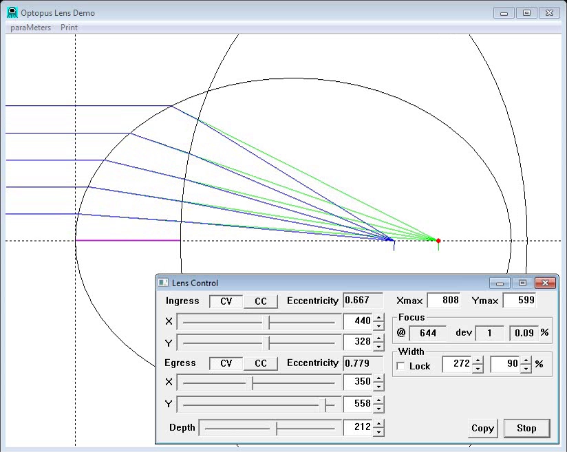
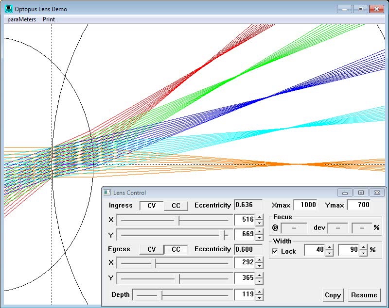
; Optopus script for basic lens demo (posted on youtube as "What's wrong
; with a Spherical Lens". Screencast recorded with Active Presenter.
; The dialog is positioned inside the drawing window at its RB corner, where
; it doesn’t interfere with the drawing if the window is tall enough. This lets
; one rectangle encompass the entire application, reducing waste in the record.

window 100,10,860,720,INRB,4,4 ; Drawing window with dialog inside window RB corner.

delay 100 ; sleep for .1 second after each drawing change type command.
width percent 90 ; Set lens width (for now and future) to 90% of calculated width.

lens 400,400,400,400,140,CVCC ; Initial spherical lens.
pause ; Suspend until script continue button is pressed.

; Show focus improvemnt as the lens becomes thinner.
delay 50 ; Quick pace for lens morphing
; Use fade command to vary the depth from 140 to 3 in 40 steps (@ 50 msec)
fade 400,400,400,400,140,CVCC  400,400,400,400,3,CVCC 40
pause
lens 400,400,400,400,140,CVCC ; Restore initial fat lens.
sleep 500

; Show focus improvement as less of the lens is used (reducing width).
delay 100 ; Moderate pace
; Use width fade command to morph the width of lens face used. This doesn't
; change the lens itself, but only the portion that we consider usable.
width fade 0 40 20 ; Using %5 steps change width from current to 40.
pause

width percent 90 ; Restore standard automatic width based on lens geometry.
lens 600,600,600,600,150,CVCC ; Large spherical lens to start ellipse morphing.
pause

; Morph spherical lens by varying ingress ellips, showing crossing and
; uncrossing of ray paths as the ellipse varies between circle and parabola.
delay 100
fade 600,600,600,600,150,CVCC  600,700,600,600,150,CVCC 10 ; > Circle
pause
fade 600,700,600,600,150,CVCC  600,600,600,600,150,CVCC  10 ; Circle again
sleep 200
fade 600,600,600,600,150,CVCC  600,241,600,600,150,CVCC 20 ; Smallest error
pause
fade 600,241,600,600,150,CVCC  600,173,600,600,150,CVCC  10 ; Parabola
pause

; Scan back over range of configurations, pointing out poor focus.
delay 50
fade 600,173,600,600,150,CVCC  600,700,600,600,150,CVCC  10 ; Parabola to circle+
fade 600,700,600,600,150,CVCC  600,173,600,600,150,CVCC  10 ; and back to Parabola
pause

; Show good foci with both faces ellipse.
delay 500
lens 410,172,563,511,36,CVCC  ; F=143 W=59 dev=0.70%
lens 410,187,563,589,36,CVCC  ; F=167 W=65 dev=0.44%
lens 413,201,293,511,36,CVCC  ; F=193 W=70 dev=0.57%
lens 410,215,563,754,36,CVCC  ; F=219 W=76 dev=0.42%
lens 367,209,185,511,36,CVCC  ; F=235 W=78 dev=0.47%
lens 368,235,49,654,35,CVCC  ; F=307 W=89 dev=0.23%
lens 462,290,49,654,35,CVCC  ; F=369 W=99 dev=0.08%
lens 635,372,70,543,54,CVCC  ; F=436 W=132 dev=0.10%
lens 635,394,50,693,45,CVCC  ; F=493 W=130 dev=0.06%
pause
lens 440,328,350,558,91,CVCC  ; F=416 W=162 dev=11.87%
pause

; Show focus improvement when egress face is flipped.
lens 440,328,350,558,91,CVCV  ; F=657 W=203 dev=0.86%
pause

; Morph to show optimum focus
delay 50
fade 440,328,350,558,91,CVCV  440,328,350,558,212,CVCV  10  ; F=644 W=272 dev=0.09%
pause

; Morph to align single- and double-face foci
fade 440,328,350,558,212,CVCV  440,328,408,411,319,CVCV 10  ; F=734 W=295 dev=0.04%
pause

; Aligned single-double face focus at various focal lengths.
delay 500
lens 408,304,348,349,332,CVCV  ; F=679 W=288 dev=0.09%
lens 365,272,315,317,291,CVCV  ; F=607 W=245 dev=0.08%
lens 331,247,316,323,224,CVCV  ; F=552 W=222 dev=0.03%
lens 301,224,327,321,181,CVCV  ; F=502 W=201 dev=0.06%
lens 251,187,318,315,107,CVCV  ; F=417 W=157 dev=0.02%
lens 204,152,251,250,94,CVCV   ; F=338 W=130 dev=0.01%
Optopus affords a wide range of configuration options and lens parameters, which can take quite a bit of time to set up. To reduce repetitive user effort I could have implemented a simple configuration capture and restore capability. I chose instead to design a scripting system, which could certainly provide this capability but would also be very useful to Thera scientists for presentations. The script language is relatively simple, providing the means to set window sizes, parameter ranges and current values but also affords some powerful commands to reduce the effort needed to prepare an animated slide show. For example, the fade command morphs a given starting lens to a final lens configuration in a given number of steps. The program divides the range of each parameter from its initial to its final value by the number of steps to automatically generate a smooth transition. The resulting animation can be a very intuitive explanation of a complex cause and effect relationship between the lens shape and beam path. I used the scripting system myself to make a public education video explaining the superiority of ellipse over both spherical and parabolic lenses.
The user interface remains active while a script is playing, enabling the user and script to work together. For example, a simple script might repeatedly (loop) morph (fade) between two lens configurations while the user varies other parameters, such as refractive index or lens width, to observe the impact over a range of configurations. The fade command can selective morph some lens parameters while leaving others untouched and open to user control. Scripts do not control the cursor, leaving it free to use as a pointer when preparing a screencast presentation.
The Optopus program has exceeded expectations. By integrating precise mathematics with intuitive display and control of complex data sets, it appeals to all of the Thera researchers. The GUI helps number-shy researchers understand the meaning behind huge lists of numbers while the direct traceability of those numbers to the display encourages the more mathematically inclined to trust the graphically presented information. Researchers who don’t really trust each other do trust Optopus. Ironically, this has led to agreement that the diffuse light collector is not feasible. Optopus reveals, to everyone’s satisfaction, that practical obstacles stand in the way of an economical realization even though the beam superposition theory appears correct.
Optopus serves Thera’s dual mission of research and education. We would have
preferred Optopus to convince us of the feasibility of this approach to solar
energy utilization but it is also useful to have compelling evidence that it is
not feasible. Thera can, with some assurance, say “don’t go there”, possibly
saving others significant time, money, and disappointment. The scripting
capability, which I added almost as an afterthought, affords an unexpected
benefit. It makes animated slide shows easy to create. Thera sees my public
lens videos as part of its mission.
[youtube.com/OneFreeBrain/What’s Wrong with a Spherical Lens?]
[youtube.com/OneFreeBrain/Mathematical Proof of Ellipsoidal Lens Focus]
The optopus program contains a substantial amount of relatively complex math, including curve fitting, ellipse slope (a differential calculus problem), ellipse-ellipse intersection (a quartic polynomial), partial derivatives, left- and right-derivatives, and non-linear interpolation. In most cases, Optopus crafts application-specific versions of generally known solutions to these problems. However, two optics problems stood out for not having generally recognized solutions. One is that the basic law of refraction (Snell’s) uses ray angles relative to an imaginary line perpendicular to the lens face, adding an unnecessary computation step to ray tracing compared to face-relative angles. The other is that no proof seems to exist for the fact (revealed to us by Optopus’s step-wise enumerated ideal lens function) that the trailing focus of an ellipse is the perfect focal point of a single-face lens when the ellipse’s eccentricity is equal to the ratio of the indices of refraction.
Having theoretical proofs for these two problems is not essential to Optopus. However, Optopus was expected to facilitate investigating unique optical problems that might be solved by methods based on fundamentals even when they can’t be solved by common methods derived from the same fundamentals but constrained by simplifying assumptions. In this light, we felt that theoretical proofs, even if not strictly necessary, would increase confidence in our new methods.
Optopus has revealed more problems than just these two but they are either not very important to our end goal or require too much effort for something nonessential. Thera researchers left it to me to discover these and decide which ones were worth pursuing. The proofs are my own original work but they may duplicate existing proofs that I was unable to find.
Given Snell’s law and the equivalent Huygen’s construction that sin(r)/sin(i) = ni/nr, where r is the refracted angle, i is the incident angle, and ni and nr are the refractive indices of the incident and refracted mediums. The angles i and r are relative to normal, an imaginary line perpendicular to the lens face at the incident point. Prove that for angles i' and r' relative to the face, cos(r')/cos(i') = ni/nr.
The given law is proven and demonstrated in an implied Cartesian coordinate system with incident ray in Q2 (90° to 180°) and refracted in Q4 (270° to 360°). It can also be proven in any of the other three quadrant relationships, the only constant being that angle increases clockwise. The face angle is normal angle + 90d, normal < i < face, and normal < r < face.
This is published as a narrated video on youtube as Mathematical Proof of Ellipsoidal Lens Focus.
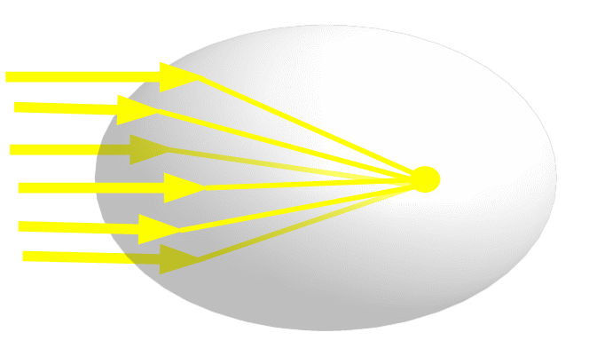
The classic lens maker’s formula that tells the focal point of a lens is deceptively simple because it applies only to a theoretical lens, which could never be made. The focal length math for a real lens with spherical faces is more complicated but still relatively tractable. However, spherical lenses produce a fuzzy focus and the math required for better shapes is difficult to solve. Consequently, aspheric lens are normally designed using brute force approximation.
One kind of aspheric lens stands out as an exception. Rotating a two-dimensional ellipse around its major axis produces a three-dimensional ellipsoid. A lens with an ellipsoidal face will precisely focus an incident beam at a point that is so easy to calculate you can almost do it in your head. Unfortunately, there are only a few situations where a single-face lens is useful but this can be the starting point for some very good two-face lenses and it is instructive in any case.
This egg shape represents an ellipsoidal glass lens. A light beam parallel to the major axis hits the end of the egg at an infinite number of points, but at every point the difference between the speed of light in air and in glass causes the beam to bend the exact amount to redirect it to the second focus of the ellipse. There is no other point like this in an ellipse or in any other figure. It is unique.
It’s too hard to trace the path of light based on its electromagnetic reality but some standard simplifications enable us to get a handle on the problem. The first is to see the beam as a flat wall moving toward and crashing into the end of the lens.
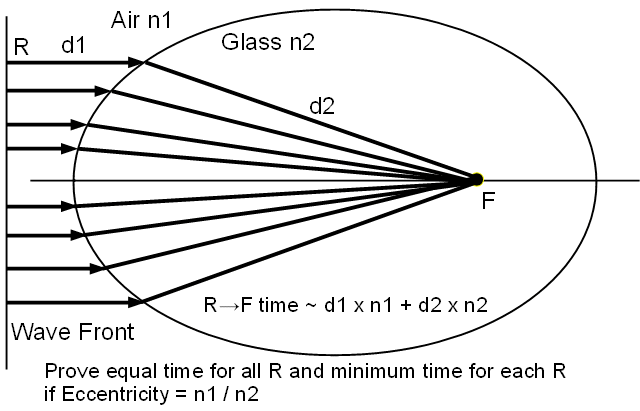
To avoid the complexity of 3D geometry we can work with a 2D slice, where the ellipsoidal lens becomes an ellipse and the wave plane becomes a line, the “wave front”. We see the beam as an infinite number of individual rays perpendicular to the wave front and, therefore, parallel to the ellipse major axis. Each ray begins at some point R at an unknown position. Anything we prove for R applies to all points and, therefore, the entire beam. Each ray travels through a distance d1 from R to the lens. Upon entering the glass, the ray bends and travels a distance d2 to a point F on the lens axis. Light travels faster in air than in glass. Refractive indices n1 and n2 indicate the relative speeds in air and glass. The longer d1 is, the more time the ray travels at the n1 speed. The longer d2 is, the more time the ray travels at the n2 speed. The total travel time from R to F is d1 times n1 plus d2 times n2. This “optical path length” is akin to traditional African maps that show distances, not “as the crow flies” but by how long it takes a person to walk them.
If the lens bends every ray to aim at the same point F, the wave front is compressed into a smaller space and the lens “concentrates” the beam. However, this is only one of two conditions that the lens must meet to “focus” the beam. The other is that every path must take exactly the same time to traverse. If this is not true then the rays lose their relative positions in time, making the beam less orderly. This smears images and makes the beam more difficult to control.
We are going to prove that both conditions can be met by an ellipse whose Eccentricity is equal to the ratio of n1 over n2, in which case the trailing ellipse focus is the lens focus.

We will be using two different but compatible definitions of ellipse. One definition is the set of points, the sum of whose distances from two fixed points is constant.
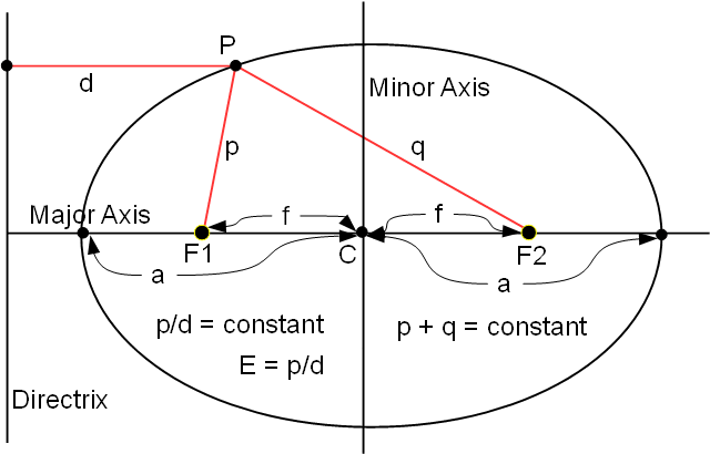
This diagram illustrates what this means. P is any point on the ellipse. F1 is the ellipse focus nearer the lens face and F2 is the trailing focus. The distance from P to F1 is p. The distance from P to F2 is q. This definition says simply that p + q is the same for all P.
The second definition is the set of points such that for each point the ratio of distance to a given point, F1, and to a line, the Directrix, perpendicular to the major axis is constant.
Referring to the same diagram, we add the horizontal line of length d from P to the Directrix. This definition says simply that the ratio of p over d is the same for all P. The definition incidentally tells us that the ratio is equal to the “Eccentricity” of the ellipse. Eccentricity essentially describes the curve of the ellipse by indicating the ratio of its major and minor axes. We would expect this to have a major influence on how the lens behaves-- and it does! Two other important items in this diagram are that the ellipse foci, F1 and F2, are the same distance, f, from the center and the major axis vertices are the same distance, a, from the center.
We can combine these details with ellipse definition (1), that p + q is the same for all points, to derive a more immediately useful relationship. By definition, P is any point of the ellipse, including this vertex. We know things about this vertex that we don’t know about other points. Its p is obviously equal to a - f. Its q is equal to f + f + a - f.
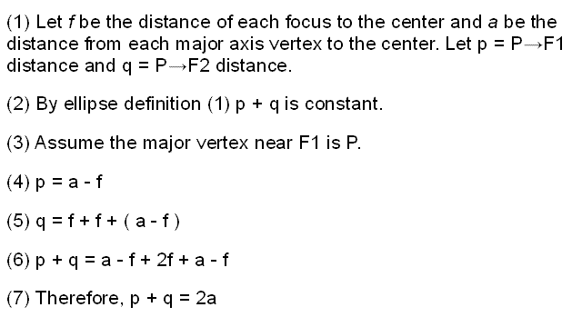
Adding equations 4 and 5 yields equation 6, which can be reduced to equation 7, p + q = 2a, which we will be using.
With these preliminaries out of the way, let’s first tackle the equal path proof.
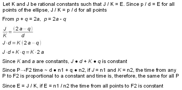
We invent two constants, J and K, for which J/K = E. We don’t know what their actual values are but since p/d equals E for all ellipse points J/K = p/d for all P. Note that J and K are constants while p and d are variables. Only their ratios are equal.
From p + q = 2a we get p = 2a - q and substituting this for p, we get J/K = (2a- q)/d. Cross multiplying this equation produces J times d = K times 2a - q. Adding Kq to both sides yields Jd + Kq = K2a. Since K and a are both constant, Jd + Kq must be constant. This looks a lot like the optical path length. If J = n1 and K = n2, the optical path length is constant. Since E = J / K, if E = n1 / n2, the optical path lengths for all P to F2 are equal.
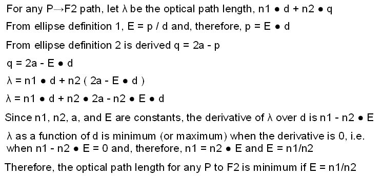
There are several ways to prove the second focus requirement, that all paths lead to F2. The most obvious would be based on how much the light bends at every point due to the angle of the ellipse face at that point. But that proof is complicated by essentially irrelevant angle calculations. A much simpler proof can be developed from Fermat’s Principle, which is that light travels the shortest optical path, the one that takes the least time to traverse.
We invent a variable, lambda, which represents the optical path length from any point P of the ellipse to F2. lambda equals n1 * d + n2 * q. From the first ellipse definition, eccentricity E equals p / d and, therefore, p = Ed. From the second definition we derived p + q = 2a and, therefore, q = 2a - p. Substituting Ed for p, we get q = 2a - Ed. Substituting 2a - Ed for q in the optical path length, n1 * d + n2 * q, we get lambda equals n1 * d + n2 * (2a - Ed) or n1*d + n2*2a - n2*Ed. Since n1, n2, a, and E are all constants the derivative of lambda over d is n1 - n2 * E.
So why do we care so much about the derivative? Because lamda is minimum or maximum when the derivative of lamda over d is 0. Fermat wants us to find the shortest optical path, i.e. minimum lambda, which occurs when n1 - n2 * E = 0, from which we get n1 = n2 * E and finally E = n1/n2. Therefore, if E = n1/n2, the optical path length from any P to F2 is minimum.